Project: Design and Fabrication of a (Solar Powered) Sun Tracker
Machine(s): Modela, Laser Cutter | Material(s): Acrylic, SMD Components, Photoresistors
Back to Main Page
Official Assignment Description: 'measure something: add a sensor to a microcontroller board and read it'
This week's project has two goals:
- Develop some experience with solar power
- Develop and test a simple method for physically aligning the face of the solar panel to be perpendicular to a moving light source
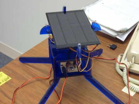
I ordered a small (2.5W) solar panel spec'ed to 8V and 310mA short-circuit. I knew this
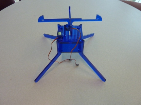
would be enough to power the microcontroller, but powering servos might require a little extra. I built a two-axis gimballed stand out of
acrylic and relied on differential readings from photoresistors to detect the relative direction of the sun. All coding was done in 'C'
using the same board I built two weeks ago. Results are summarized as follows:
- The electronics and tracking algorithm worked well. A low pass filter helped reduce chatter in the servos.
- The solar panel did not supply enough power to operate the servos. Perhaps a better approach would be to use the solar
panel to charge a battery. The microcontroller could then turn on periodically to perform a single measurement and execute a single
command (powered by the battery).
- The gimbal stand should be redesigned for better balance (so that no power is required to hold a single position).
Design and Fabrication
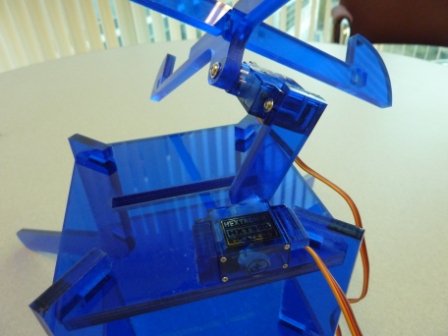
Step 1: Design the gimballed stand. It uses two servos to change the angle of the face of the solar panel. I used acrylic...which
was brittle and rather unenjoyable to work with...but it was free :). Parts were designed in SolidWorks and cut on the laser cutter.
solar tracker stand.SLDPRT , solar stand dxf revised.CDR
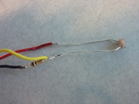
Step 2: Make sensor circuit (photoresister with bias resister), solder leads to board, and mount on stand.
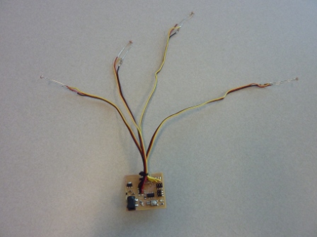
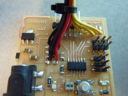
Step 3: Write C program. It takes four single ended analog readings, subtracts the values in software, converts the readings to
angle commands for the servos (5V pulses of 1000us to 2000us), and sends commands to all four servos every 25ms. Differential readings are
passed through a digital low pass filter to reduce bandwidth (the sun doesn't move very quickly..). Capability to print values
to serial port are also included in the code.
solar_tracker.c
Step 4: Upload and test. I bought a halogen light from Home Depot to be my sun (I don't get outside much).
Tips and Lessons Learned
-
Solar cells require *bright* sunlight to work well! They also aren't good at supplying bursts of current...better to use the solar cell
to charge a battery; the battery will be much better at supplying higher current.
-
I was never able to make differential analog readings (in hardware). It worked ok for positive readings, but negative readings were written
to the ADC register as 0b100111 (39). This will be a source of future debugging.
-
Acrylic is a tough material for press-fit projects. It's brittle, varies about 1/100th of an inch in thickness, and doesn't get cut cleanly
by the laser cutter (as in, kerf can vary about 1/100th of an inch with depth for a quarter inch piece). Oh, and the power output
of the laser cutter appears to vary noticeably over different locations on the cutting bed. Be aware.
Back to Main Page